Posts

Showing posts from August, 2017

Mikrotik Router OS CAPsMAN Wifi Controller Simple Configuration

Image
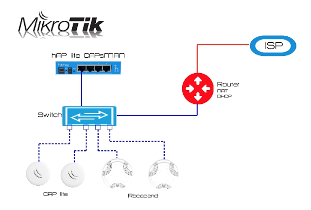
Mikrotik Router OS CAPsMAN Configuration only bridge mode with external DHCP server and NAT service You can deploy CAPsMAN wireless controller on any Mikrotik RouterOS hardware (for instance Haplite series routers) 1st step is to check our RouterOS image version, it should include wiressless package (check System>Packages). OS version on CAPsman controller should the same as in Access Point. You can upgrade the version manual. Go to the System>Packages , then simply drag and drop your previously downloaded imge. After I would recomend to reboot it from CLI / system reboot and then just run / system routerboard upgrade and again reboot it. Then we can check the version / sys rou print . 2nd step is to create bridge interface which should include our physycal interface or several interfaces, so we create bridging between our physycal interfaces or if it's only one interfaces then it will be put into bridge mode. Let's check our interfaces:

HPE MSR series router NAT, DHCP, SSH config

Image
1. NAT Configuration    1.1. Define Access List [Router] acl basic 2001  [Router] step 1 [Router] rule 0 permit [Router] rule 10 deny 2. Interfaces Configuration    2.1. External (WAN) interface configuration [Router] interface GigabitEthernet 0/0/0 [Router] ip address 10.163.195.2 255.255.255.0 [Router] nat outbound 2001     2.2. Internal (LAN) sub-interfaces configuration [Router] interface GigabitEthernet 0/0/1.2 [Router] ip address 192.168.1.2 255.255.255.0 [Router] vlan-type dot1q vid 2 [Router] interface GigabitEthernet 0/0/1.3 [Router] ip address 192.168.2.2 255.255.255.0 [Router] vlan-type dot1q vid 3 [Router] interface GigabitEthernet 0/0/1.4 [Router] ip address 192.168.3.2 255.255.255.0 [Router] vlan-type dot1q vid 4 3. DHCP Server Configuration     3.1. Enable DHCP service on router [Router] dhcp enable     3.2. Define dhcp settings for vlan 2 [Router] dhcp server ip-pool vlan 2 [Router] ne

JNCIA Lab Guide

Image
GET YOUR JNCIA LAB manual 

JUNIPER WLC CONFIGURATION AND HP WLAN 850 CONFIGURATION OVERVIEW

Image

DHCP Relay Configuration on Juniper SRX 210 using Ubuntu 12.04 DHCP Server

Image

Ubuntu IPSec/L2TP VPN Configuration

Image

How to limit the traffic rate (bandwidth) on Juniper SRX 210 interface acting as switch

> First create a l3-interface to the VLAN you are trying to limit >This way you will apply rate limit filter on transit traffic going in / out of VLAN e.g. 1) Filter Definition firewall { policer 2Mbps { if-exceeding { bandwidth-limit 2m; burst-size-limit 100k; } then discard; } filter Filter-2Mbps { term a { from { source-address { 192.168.1.0/24; } } then { policer 2Mbps; accept; } } } } 2) Apply on VLAN Interface interfaces { vlan { unit 0 { family inet { filter { output 2Mbps; } address 192.168.1.1/24; } } } }

How to disable LCD operational menu on Juniper EX 3200 / EX 4200 switches

In order to prevent factory reset on switches with LCD operational menu you can use the following command: # set chassis lcd fpc 0 maintenance-menu disable

Block ICMP on Juniper SRX 210

Assume you have SRX connected to a VLAN, example 192.168.1.0/24. SRX has IP in that subnet, like 192.1168.1.1. You have PCs in that same VLAN/subnet and try to block ICMP between those PCs, so you want to effectively block 192.168.1.5 from pinging 192.168.1.6. So is it possible on SRX 210? Well, you may think that it should be done with some polices like: match source address my PC match application [junos-ping, junos-icmp-all.....] match destiantion address any then reject > The result of this policy - you won't be able to ping external hosts (public IPs) but you can ping your local hosts in vlan. This can not be accomplished via policies btw since the PCs are in the same vlan. Another posibility is to apply firewall filter into vlan confiuration: set firewall family inet filter icmp term 1 from protocol icmp set firewall family inet filter icmp term 1 then discard set firewall family inet filter icmp term 2 then accept set interfaces vlan unit 2 family inet filter input icmp

Steps to configure interface-range on Juniper EX/SRX devies

Configure vlan:   user@juniper# set vlans voip vlan-id 10   Configuring the interface-range "test" to be a part of a vlan (voip): user@juniper# set interfaces interface-range test unit 0 family ethernet-switching vlan members voip Adding member interfaces (actual physical interface) to the interface range: user@juniper# set interfaces interface-range test member-range ge-0/0/0.0 to ge-0/0/10  user@juniper#   commit configuration check succeeds commit complete

Install Junos with USB

You discover that your Junos EX or SRX device does not complete normal boot up. The image seems to be corrupted for some reason, such as a continuous power failure. If this occurs, don’t worry, you can get it back up within few minutes using the USB port. Step 1. Get a USB flash drive. Copy the Junos image to the USB drive (without creating folders). Use FAT file format if the USB size is less than 2 GB. Use FAT32 if the USB size is greater than or equal to 4 GB. The example below uses the file image junos-srxsme-10.4R1.9-domestic .tgz. Step 2. Insert the flash into an EX/SRX USB port. Step 3. Reboot the device. When Junos boots up, you will see the message : Press Space to abort autoboot Do nothing. A little while later, you will see: Hit [Enter] to boot immediately, or space bar for command prompt. Press the space bar. You will be at loader mode; the prompt should be loader>. If the prompt is > , type >boot to make it loader>. Step 4. Now type the following command: lo

DHCP & NAT on Juniper SRX 210 for all interfaces

Assume that we need to distribute the Internet on SRX210 using DHCP, NAT services for all interfaces. Our provider issued us a public IP address (for ex. 192.168.1.1) which we gonna assign to untrust zone on ge-0/0/1 interface. Interfaces fe-0/0/2 through fe-0/0/7 we shall assign to trust zone, include them in routed vlan and configure for dhcp service. Let's see how it will be: set system services dhcp pool 172.16.1.0/24 address-range low 172.16.1.33 set system services dhcp pool 172.16.1.0/24 address-range high 172.16.1.64 set system services dhcp pool 172.16.1.0/24 default-lease-time 3600 set system services dhcp pool 172.16.1.0/24 domain-name juniperlab.info set system services dhcp pool 172.16.1.0/24 name-server 8.8.8.8 set system services dhcp pool 172.16.1.0/24 router 172.16.1.1 set interfaces ge-0/0/1 unit 0 family inet address 192.168.1.10/24 set interfaces fe-0/0/2 unit 0  family ethernet-switching vlan members dhcp set interfaces fe-0/0/3 unit 0 family ethernet-switchin

Interface Rate Limit on Juniper EX switches

1. Configure the policer root@juniperlab# set firewall policer Policer_2M if-exceeding bandwidth-limit 1M root@juniperlab# set firewall policer Policer_2M if-exceeding burst-size-limit 2k root@juniperlab# set firewall policer Policer_2M then discard 2. Configure the firewall filter root@juniperlab# set firewall family ethernet-switching filter Limit term 1 then accept root@juniperlab# set firewall family ethernet-switching filter Limit term 1 then policer Poicer_2M 3. Apply filter on interface (can be any interface as required) root@juniperlab# set interface ge-0/0/24.0 family ethernet-switching filter input Limit Note: Remember that EX series switches apply rate limit only on ingress.  

Implementing QoS in Juniper SRX 210

There are a lot of implementing QOS scenarios and I won't tell you about all. Depending on configuration we can apply different types of classifiers, policing, simple filters and so on. I just wanna show you the config for SRX 210 when it's required to prioritize voice over data traffic and due to configuration there is no possibility to apply MF classifiers, filters, policers. Forwarding Classes Step 1: Define egress queues for voice, data, best-effort, network-control: root# set class-of-service forwarding-classes queue 0 voice-class root# set class-of-service forwarding-classes queue 1 data-class root# set class-of-service forwarding-classes queue 2 best-effort root# set class-of-service forwarding-classes queue 3 network-control Classification BA Classifiers Step 1: Enter into COS classifiers hierarchy, and create classification profile based on DSCP: root# edit class-of-service classifiers dscp traffic_classifiers Step 2: Import default code-points defined by

Juniper SRX 210 Voice over Data traffic priority config

Image
NORMALLY, PACKET CLASSIFICATION OR MARKING IS PERFORMED AT INGRESS AS IT IS NEEDED TO ENSURE THE CORRECT TREATMENT OF THE PACKETS IN THE SUBSEQUENT PROCESSING STAGES, WHILE PACKET QUEUING/SHAPING IS USUALLY PERFORMED AT EGRESS SINCE IT IS GENERALLY WHERE BANDWIDTH LIMITATIONS OCCUR, FORCING PACKETS TO BE EITHER DROPPED OR QUEUED. 1.1 BA Classification To apply a BA classifier, first define a classifier, a list of code points (values of the DSCP or EXP bit field), and the associated forwarding classes and packet loss priorities. Once the classifier is defined, it can be applied to a logical interface. The loss priority and forwarding class will be determined by querying the classifier table for that interface, using the ingress DSCP/EXP bits of the packet as the index value (the determination of which bits to query is based on the protocol family MPLS, IPv6, or IP). The classifier defines IP precedense value 101 as voice traffic and 000 as data traffic. set class-of-service class